- Text Size:


3 August 2020
A case study in moving from YAG to fibre lasers - Pyramid Engineering and SPI Lasers
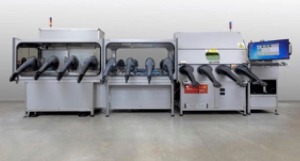
In 2019 SPI Lasers were approached by Pyramid Engineering to supply an evaluation laser for a new welding system being developed for a telecommunications customer (Fig 1).
As a leading designer and integrator of high precision welding systems for the hermetic sealing of metal-can semiconductor and electronic packages, Pyramid were looking to replace their existing flashlamp pumped Nd:YAG laser sources in order to offer their customers enhanced levels of speed, productivity and cost effectiveness as well as greater versatility with fiber lasers.
The systems provided by Pyramid are bespoke, designed to suit a customer’s particular requirements incorporating turnkey environmental systems covering gloveboxes, airlocks, vacuum gas-bake ovens, 3-way motion and complete with process control equipment including various levels of automation.
 In SPI Lasers they found the ideal range of products based on the redPOWER CW range of high power fiber lasers, offering the perfect blend of quality, repeatable laser sources combined with excellent customer service. Something that Pyramid were particularly keen on given how closely they would need to work with their chosen supplier on this initial system build.
A challenging application
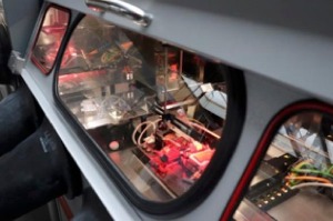
The majority of Pyramid’s laser welding systems utilise at least one glovebox, which allow for a controlled or conditioned atmosphere, which is particularly challenging for welding applications.
The existing YAG solution used a fixed optical weld path and precise CNC motion-controlled welding table. SPI Lasers‘ solution was to introduce oscillation welding (a controlled spiral movement of the laser generates the weld pool), which uses a single mode high power laser with a scanner to rapidly move the laser beam to generate the weld pool. The high beam quality and small focused spot size creates a controlled key hole that minimises heat input into the part. The benefits of this process being that the weld depth and width can be controlled independently, and scanner parameters can be adjusted to control the weld shape. Control of the weld pool through oscillation can also greatly reduce weld spatter, resulting in higher quality welds as well as avoiding cracks in the weld.
Pyramid’s focus is on delivering their customers the very latest technically advanced equipment, manufactured to the highest possible standards. This is why they were keen to investigate alternative laser sources and processes for their system(s); it quickly became apparent that a fiber laser and the oscillation welding process was indeed more suitable to Pyramid than their existing solution for a number of reasons:
Oscillation weld vs fixed optic weld
- 10 x faster welding speed from a fiber laser vs YAG
- Part fit up 3x more forgiving in terms of seam gap and offset
- Independent control of penetration depth and seam width
- Better welds both structurally and visually
- Cost savings from both laser source and beam/part manipulation
- Lower heat input per unit length of weld vs YAG process
FIber laser vs YAG Laser
- 30 percent wall plug efficiency vs. circa 2 peercent for lamp-pumped YAG
- Cost savings as there are no flash lamps to be replaced
- Maintenance operation is considerably reduced
- Minimal spare part requirements – SPI Lasers utilise ‘Fit & Forget‘ technology Reduced cooling and chiller requirements o Substantial reduction in laser footprint
- No requirement for periodic alignment of the laser
The evaluation
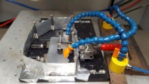
A test station was created (Fig 2 and 3) and fitted with a redPOWER 2kW single mode laser (M2 less than 1.1), with beam delivery optics of a 100mm FL collimator and a 255mm FL scanner objective lens, which generated a 51um (1/e2) focal spot size.
The trial application was to successfully complete a hermetic fillet weld of an aluminium lid (grade 4047) onto a complex aluminium body (grade 6061-T6) which dictated a number of intricate and complex shaped welds.
Argon was used as a shield gas which was fed to the workpiece through 2 delivery tubes seen in the images below; the workpiece was enclosed in a ‘bath‘ to hold the shield gas around the part.
Initial trials proved successful by identifying a range of parameters that could weld these materials with good quality.
 The system was designed specifically to manufacture the customer’s complex product, ultimately destined for the telecommunications industry. Two critical factors were specified:
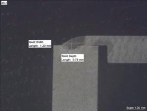
1. the weld penetration was to be kept between 0.5mm – 0.75mm
2. minimise heat input due to package containing delicate optical components.
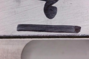
Using the oscillating (wobble) welding head, the weld path and pattern of weld can be configured; using a 50micron spot size the laser beam can be ‘wobbled’ to a width of 2mm, in a configurable path such as circular, linear or infinity symbol. The pattern was optimised to meet the customers critical factors (Fig 4.1 and 4.2).
Pyramid maintained a high welding speed over the whole of the unusually shaped package as it fitted within the scanner’s field of view, meaning that other than the scanner, there were no moving parts. An integrated vision system delivers pre-weld and, where required, post-weld verification.
 Conclusion
The project showed that close cooperation on tackling the challenging requirements resulted in a successful outcome that has delighted the end customer. It has highlighted the significant benefits of using fiber lasers verses Nd:YAG lasers as well as the value of oscillation welding in tailoring weld profiles to meet specific requirements.
If you have a challenging welding problem or are looking for a bespoke manufacturing system for your business and need expert assistance contact Pyramid Engineering or SPI Lasers and start your journey towards enhanced manufacturing productivity today.
Laser Welding - YAG vs fibre laser (video link)
Contact: Pyramid Engineering:
e-mail: enquiries@pyramideng.com
web: www.pyramideng.com
Contact: SPI Lasers
e-mail: sales@spilasers.com
web: www.spilasers.com
Figure 1 – The finished system
Figure 2 – SPI Test station with enclosed bath and Argon gas delivery tubes
Figure 3 – Image to show set up of Laser Glovebox
Figure 4.1 – Image of welded Package, circular weld path
Figure 4.2 – Image of welded Package, section cut through.